uml-sp
Object-oriented simulation language UML2 SP
This project is maintained by vgurianov
Queueing theory
1. M/M/1 Queueing System
The M/M/1 queue is a single server queue with an infinite number of waiting positions where the arrival process is Poisson and the service times are exponentially distributed. The barber simulation is a classical example of queueing theory.
Problem domain
There is a single-chair barbershop.
From when it opens in the morning until it closes, customers arrive every 20 ± 10 min at random times.
If the barber is not busy, he serves a customer immediately; otherwise they must wait in a queue (FIFO order).
The time needed to serve each customer is 19 ± 5 min also random.
It’s necessary define an average length of queue and an average time of waiting.
A conceptual model in UML2 SP is an analysis class diagram. This diagram considered as ontology. The analysis class diagram of barber model depicted in Fig.1.
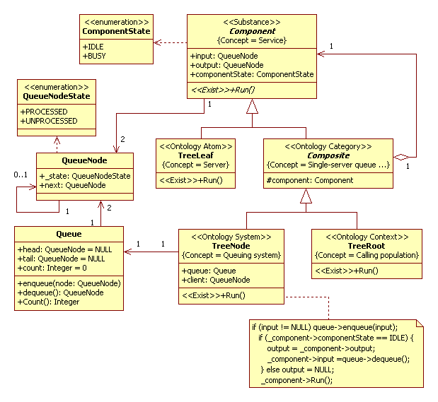
Figure 1. Analysis class diagram of barber model
Description of a computational semantics
The object of TreeNode class and the object of TreeLeaf class interact according Producer-Consumer pattern [1]. The Producer-Consumer pattern is standard solution for interaction two and more threads.
Description of an problem domain semantics
The key elements of queueing systems are the customers and servers. The term “customer” can refer to people,
parts, trucks, e-mails etc. and the term “server” clerks, mechanics, repairmen, CPUs etc.
Further we shall accurately define these concepts.
Service
The “Component” frame defines Service concept (notion). Service is a server or a queuing system.
Example, customer service in shopping is the provision of service to customers before, during and after a purchase.
The frame has “input” and “output” slots. It is input and output of queuing system. Those attributes has type “QueueNode”.
It is defined of “Customer”. The “QueueNode” class isn’t a frame.
The frame has “componentState” slot. It is state of a queuing entity.
Server (barber)
The “TreeLeaf” frame defines Server concept. The Run method is realization abstract operation Run.
This operation defines a rule of change of slots value.
Single-server queueing system
The “Composite” frame defines Single-server queueing system concept. The Ontology Category stereotype defines a group (category) of a queuing system. In this model it is the single-server queueing system.
Queuing System (barbershop)
The “TreeNode” frame defines Queuing System concept. It is main notion in the Queuing Theory. The frame has “Queue” slot. It is define “Customer queue” concept. A type of the slot is Queue. The “Queue” class is not a frame. The frame has “Client” slot. This slot defines “Client served”.
Calling population
The “TreeRoot” frame defines Calling population concept. The population of potential customers, referred to
as the calling population, may be assumed to be finite or infinite.
It is a boundary and initial condition for the queuing system.
The simulation model in C++ code:
baseClassOfBarberProject.h, baseClassOfBarberProject.cpp
2. General Queueing Theory in UML2 SP
In general case Component and Composite classes in Fig.1 linked as one to many. For reification this link we use ItemOfList class. In simple case it is linked list. It is depicted in Fig.2.
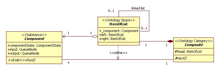
Figure 2. The reification
Usually queueing networks classified as open, closed or mixed network. However, in UML2 SP a classification is a tool to decomposition queueing network and the classification define elements of decomposition. First element of decomposition is multiphase queueing network. As instance is Tandem (Open) Queueing Network or a machine shop. This is a special case of a simple open network with N queues where jobs move sequentially from S1 to SN servers and then leave the system. It is element describe as SequentialAccessComposite class. Second element of decomposition is G/G/s queueing system. In this case, element has one queue and N parallel servers. Servers work as concurrent threads. This element has store-&-forward node (switch or router). The node route jobs to servers. It is element describe as DirectAccessComposite class. The classification is depicted in Fig.3.
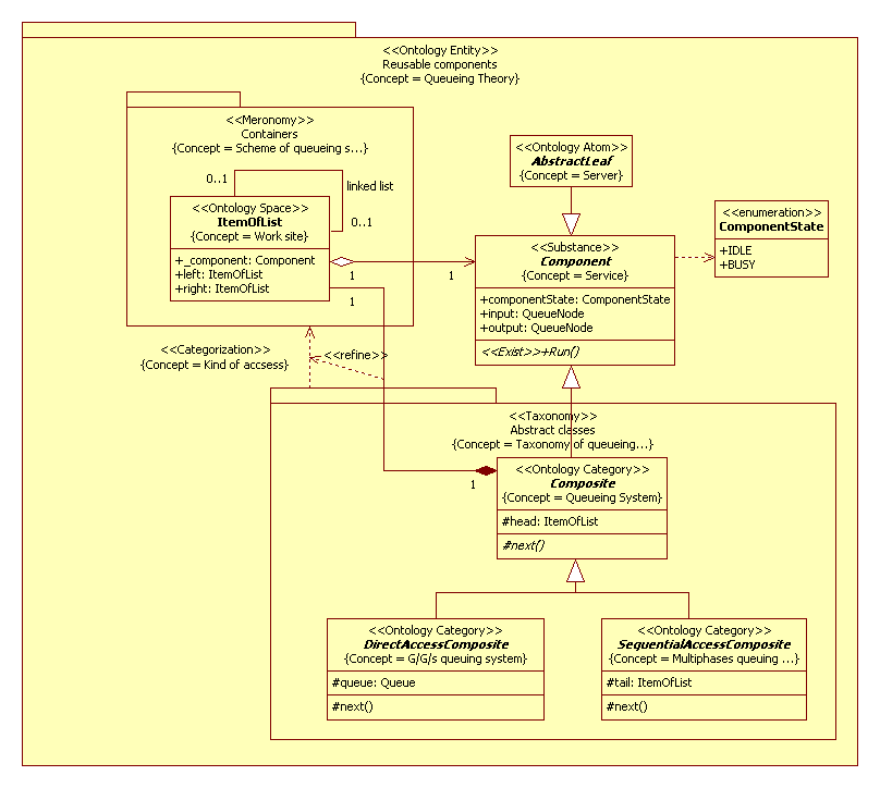
Figure 3. The classification of a queueing system in UML2 SP
In UML2 SP an architectural diagram is a conceptual graph
and contains packages and links (dependences) between them. Packages and dependences define concepts.
Further we shall discuss new frames and new concepts.
Queueing theory
The “Reusable components” package defines Queueing theory concept. In UML2 SP a theory include base elements of queueing system and classification of systems.
Service
Definition of concept as in Fig.1.Service is a server or a queuing system.
Server
The “AbstractTreeLeaf” frame defines Server concept.This definition of concept is like Fig.1 but a statistical distribution can be M,D,E, and G for daughters of class.
Categorization
Classification of queueing systems is a mapping of elements of “Abstract classes” package to “Containers” package and it is a dependency of packages. For each taxon assign one scheme. It is a functor [2].
Scheme of queueing system
The “Containers” package define Schemes of queueing systems (similarly Fig.4). In our classification exist one scheme.
Work site
The “ItemOfList” frame defines Work site concept, i.e. cells to service, and links between them. It is a configuration space of system.
Taxonomy
The “Abstract classes” package defines Taxonomy of queueing systems and consist three abstract classes.
Queueing system
Definition of concept as in Fig.1 but class has “next” method for move to members of system.
G/G/s queueing system
The “DirectAccessComposite” frame defines G/G/s queuing system concept. The frame has “queue” slot. It is definition of queue as in Fig.1.
Multiphase queuing system
The “SequentialAccessComposite” frame defines Multiphase queuing system concept. The frame has “tail” slot. It is a result works this system.
A typical example for used this classification are discussed in the subsequent section.
3. Example of Decomposition of Queueing System
Problem domain
In Fig. 4 present a queueing system consist four servers. Server S1 is a CPU, S2 is Hard Disk (HD). Both a CPU and HD are parts of computer. Peripheral device (PD) consists at S3 and S4 servers; S3 is a printer, S4 is a fax.
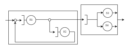
Figure 4. Example of queueing system
Continuing in the same way, we must define concrete classes for the model. Model the queueing system is depicted in Fig.5
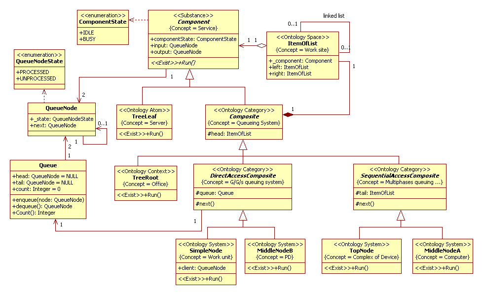
Figure 5. The Class diagram
Description of a computational semantics
The objects of daughters of Component class interact according Producer-Consumer pattern [1]. There are ten concurrent threads in total.
Description of an problem domain semantics
The TreeRoot class is model of environment, in our case it is a office. SimpleNode class is G/G/1 queueing system. MiddleNode and TopNode classes are levels of decomposition of system. These classes used to assemble the queueing system from Fig.4. This communication diagram is depicted in Fig.6
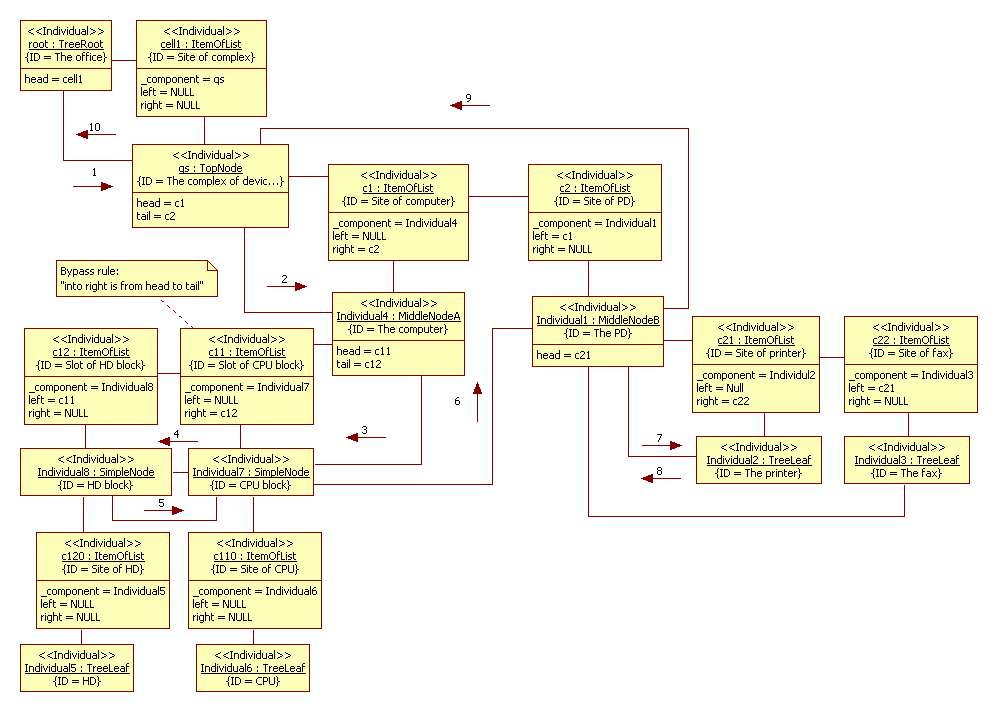
Figure 6. The communication diagram
Assemblage of the queueing system is
SimpleNode *s1, *s2;
s1 = new SimpleNode; s2 = new SimpleNode;
// ** Computer
MiddleNodeA *ms = new MiddleNodeA(s1,s2);
// ** Peripheral device
TreeLeaf *s3, *s4;
s3 = new TreeLeaf; s4 = new TreeLeaf;
MiddleNodeB *md = new MiddleNodeB(s3,s4);
// ** Complex
head = new ItemOfList; head->_component = ms;
head->right = new ItemOfList; head->right->_component = md;
head->right->left = head;
tail = head->right;
In addition, other examples of object-oriented models of queueing system see in [3,4].
The simulation model in C++ code:
BaseClassesOfTheoryProject.h, BaseClassesOfTheoryProject.cpp
References
- Mark Grand, Patterns in Java, Volume 1: A Catalog of Reusable Design Patterns Illustrated with UML, Second Edition, John Wiley & Sons, 2002
- Shreider Y.A., Sharov A.A. Systems and models. - M: Radio and communication, 1982 - 152 p. (Cybernetics)
- Trub I., Trub N. Simulation modeling of computer systems. Training workshop. LAP Lambert Academic Publishing. - 2015. - 135 p.(in Russian)
- Trub I.I. Object-oriented simulation in C ++: Training course - Spb .: Peter, 2006. - 411 p.